| | | | | | | |
| All rights reserved. |

| | | | | |
| Layout |
These pages cover different aspects designing a VPPEM instrument
| Instrument Design |
The VPPEM endstation is located as the last experimental
station on SST1 and SST2, terminating the beamlines.
A layout diagram of the endstation portion of the NIST
beamline suite at NSLS-II is shown here.
station on SST1 and SST2, terminating the beamlines.
A layout diagram of the endstation portion of the NIST
beamline suite at NSLS-II is shown here.
Endstation portion of NIST beamline suite. VPPEM is located at the end of the SST-1 and SST-2 beamlines.
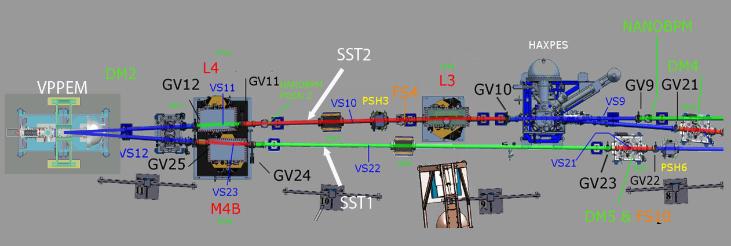
Two photon shutters PSH3 and PSH6 that serve to isolate
VPPEM from the main beamline sections are located
upstream of the VPPEM beam forming mirrors M4B and
L4.
VPPEM from the main beamline sections are located
upstream of the VPPEM beam forming mirrors M4B and
L4.
The 7-ID beamlines are:
SST-1 : Soft x-rays, elliptical polarized undulator (EPU). X-rays
from 100 eV to 2.2 keV, with focus spot sizes from 2cm to 10µm.
SST-2 : Tender x-rays, elliptical polarized undulator (EPU) X-rays
from 2.0 keV to 7.5 keV with focus spot sizes from 10-50µm.
These beamlines enter the VPPEM at 6.6 degrees apart (+ 3.3) in the
horizontal plane after deflection and focusing with the L1 and M4B mirrors.
The beamlines are directed horizontally into the VPPEM input ports.
subtends an angle of approximately 0.76 degrees in the horizontal
direction and 0.4 degrees in the vertical. SST-2 subtends an angle of 0.29
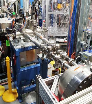
The dual beam lines enter the VPPEM endstation through two ports at the
back of the CHA as shown in here.
The CHA has apertures for the beam paths through the CHA hemispheres
and baseplate. The dual beams come to coincident foci at the sample
position centered on a six way 6” CF cross.
direction and 0.4 degrees in the vertical. SST-2 subtends an angle of 0.29
The dual beam lines enter the VPPEM endstation through two ports at the
back of the CHA as shown in here.
The CHA has apertures for the beam paths through the CHA hemispheres
and baseplate. The dual beams come to coincident foci at the sample
position centered on a six way 6” CF cross.